This page explains a trick for capturing fleeting events with electronic monitoring systems. It goes on to provide some circuit details.
What is a "fleeting event"? Why is it hard to "capture"?
"Fleeting" is a relative term. If you dedicate a small system to the job, you could "watch" a cookie jar, and detect your 10 year old snatching a cookie from it, even if he only had the lid off for two seconds. The nice scientists at CERN detect events that last micro-seconds.
"Fleeting compared to what?" is the question.
Compared to the resources you want to devote to the monitoring.
A system that checked if the cookie jar was open once a minute really wouldn't be good enough.
Why can't you check it, say, every half second? You could, of course... if the relevant electronics weren't doing anything else.
I have a system ((link)) that checks four temperature sensors, a rainfall sensor, windspeed, barometric pressure, the state of my burglar alarm... and more! It presents graphs of the readings to anyone who cares to visit a web page.
Obviously, the system doesn't watch every sensor all of the time. The temperature sensors are checked about once every 5 minutes. I will take the chance that the temperature in the living room won't rise 8 degrees and then fall back again to where it was before between two of the periodic checks.
That really wouldn't "do" for watching the cookie jar, would it?
You can make fancy "latching" circuits which will "remember" an event. But then you have to deal with clearing the latch each time you look at it. And my trick gives you more information than a latched bit would, anyway.
I start by putting a "switch" on the cookie jar. Lid on: switch closed. Lid off: switch open. (Designing a suitable switch is an interesting challenge in itself.)
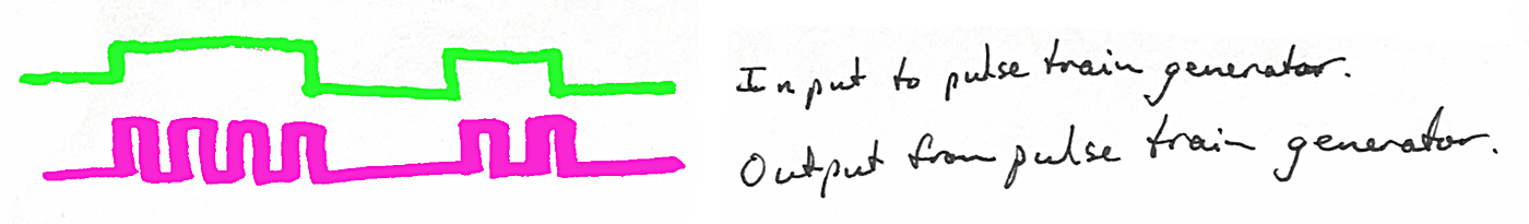
I then connect the switch to a small circuit (presented further down this page). That circuit has one output. That output stays in one state when the switch on the cookie jar is closed.
When the cookie jar switch is open, my little circuit puts a pulse train on the output. In other words, the output goes on/ off/ on/ off... until the cookie jar lid is closed again.
Cost of my circuit? Under $5.
The on/off/on/off happens three times in two seconds. (The exact frequency isn't critical... and you can make it whatever you want just by using a different resistor or capacitor in the right place.)
Now comes the clever bit: I connect the output of my circuit to a counter.
A counter is a circuit... there are many out there... which count ons and offs. It has one input. The output of a counter can take many forms. As long as your counter has an output that you can read with whatever system runs your big monitoring system can read, you're "done".
Me? I use Arduinos and 8266s for such things. They have built-in counters! I've written about how to use the hardware counter inside an Arduino. I already have an 8266 involved, because it serves the web page with information about various things. Adding the cookie jar report is trivial.
Now the monitoring software can check the number in the counter as infrequently it likes, and still "see" even a brief opening of the jar....
Job done!
All we need is a simple oscillator. The traditional way to create one is the 555 integrated circuit, which has been around since 1972. That chip is called a "timer", not because it can tell you the time of day, but because with it, you can create pulses of a specified length (specified "time long"), or chains of pulses with (within reason!) whatever properties you want... any "time on", any "time off". ("Pulse": a cycle from off to on to off again.)
When it is set up to create a chain of pulses, the thing we want, the timer is said to be "configured as an astable". (It can also has monostable and bistable operating modes.)
But an astable timer is essentially just a simple oscillator. And, vital for us, we can "turn" the stream of pulses on and off with a single input to the 555.
Here is the basic circuit, courtesy of Wikipedia...
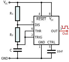
The rest of this page is just an elaboration on that theme, with some notes on specifics, and on how you would connect it up to the context I set out at the start of this. I do not, here, go into any of the related software. If you want to know about that, start at the page I already cited about using an Arduino's built in counter.
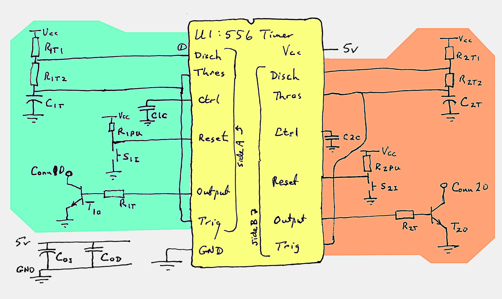
In the big diagram below there are columns marked "555" and "556". The 556 is a dual version of the 555... two 555s in a single package. We won't, in this project, be using both sides of the 556, but the diagram covers what you should do with the unused pins if you don't have other uses for them.
The following tells you all the things you need to hook up...
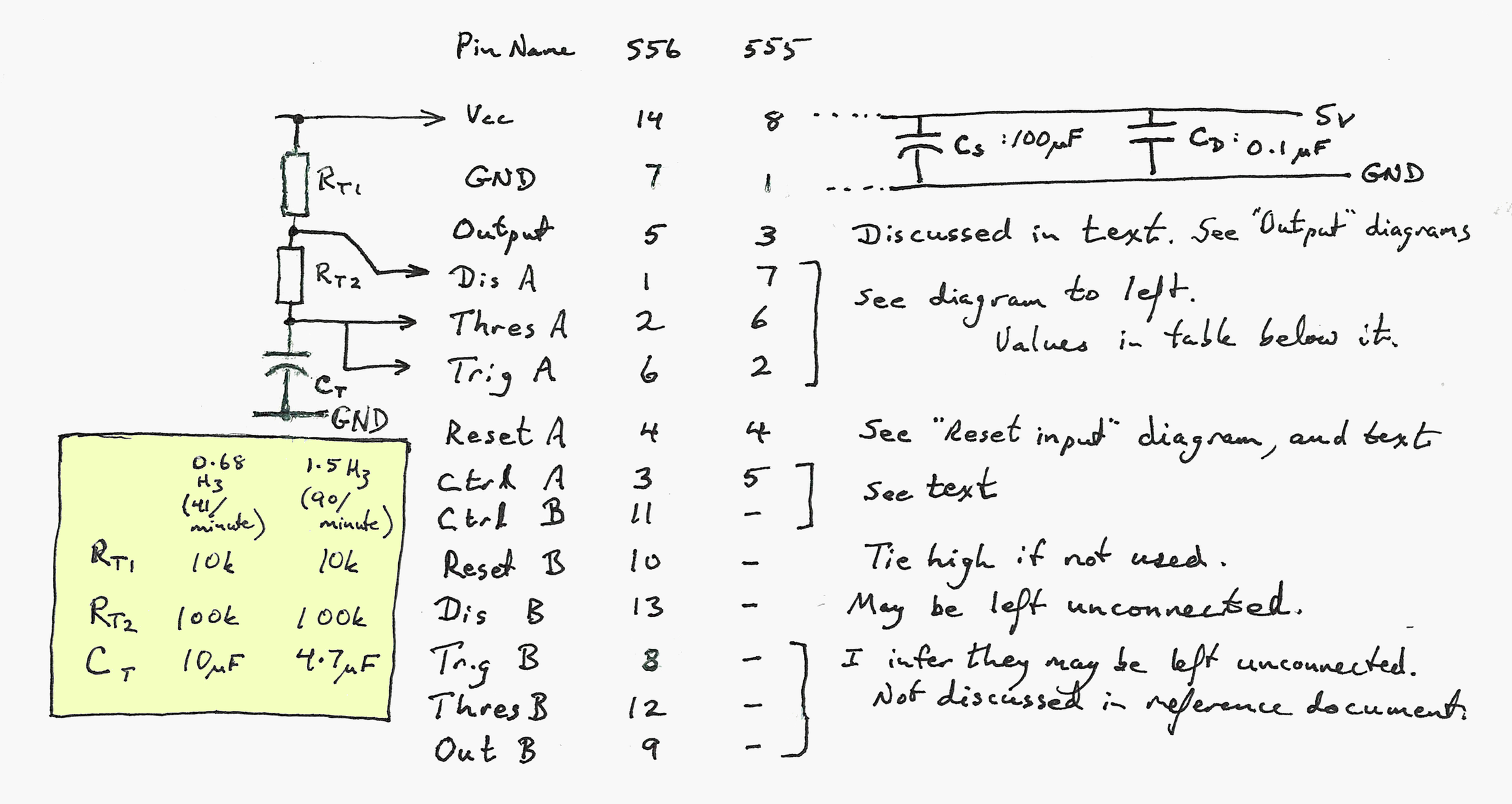
Capacitors on the supply: Cs is there to smooth the power supply, suppress things that might otherwise arise. It was suggested by the very helpful guide to using 555 timers from dlb.sa.edu.au.. as was most of everything else here about how to use 555 timers. But the idea of using a stream of pulses to "catch" a transient event was mine!
Rt1, Rt2 and Ct... connected to Dis A/ ThreA/ Trig A: The values chosen for these three components determine frequency and duty cycle of the pulse train. If you want a different pulse rate than the two offered with the values in the table, consult the reference just cited.
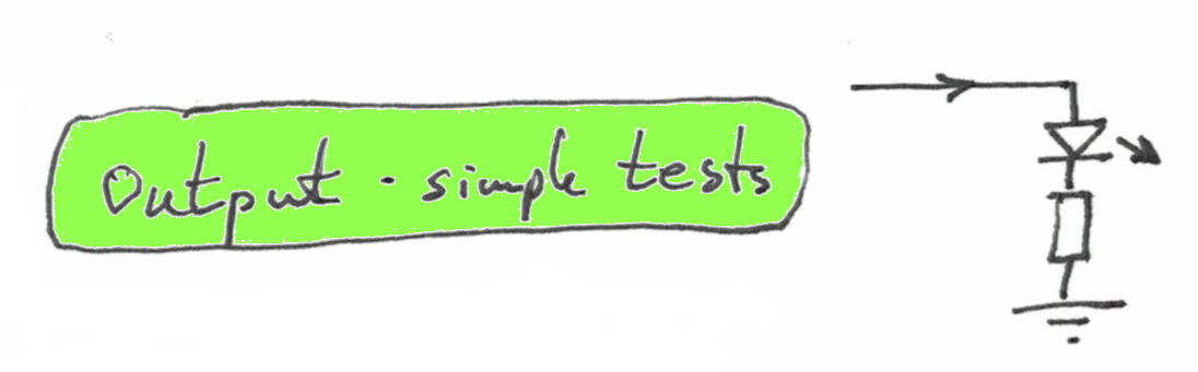
"Output" pin- simple circuit: The simplest output is as follows... and this is just to test that the circuit does deliver a string of pulses when the switch on the cookie jar is open, and that the output is low whenever the cookie jar switch is closed.
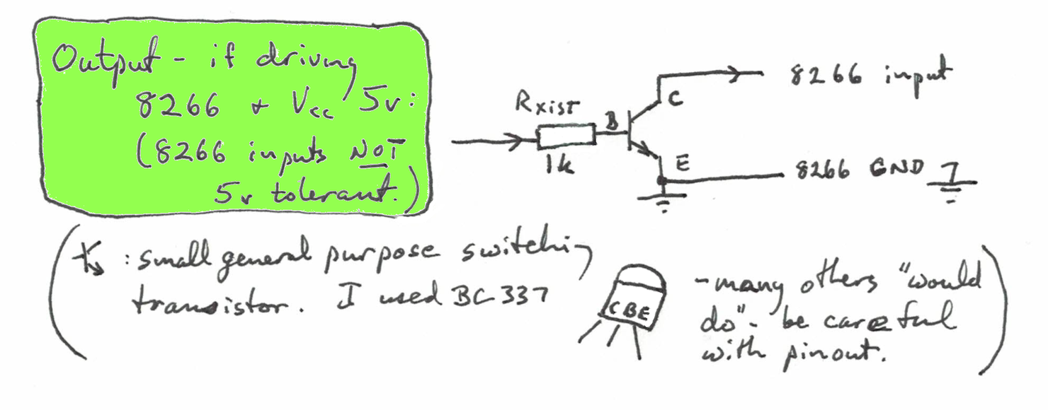
"Output" pin- connected to 8266: I ran my circuit at 5v, because 5v was readily available to me.
But! The 8266 input that I wanted to connect the oscillator's output to is not 5v tolerant. (No 8266 input is 5v tolerant.) But a simple transistor did the voltage level shifting for me without hassle, as follows.
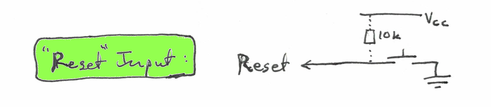
"Reset" pin: The state of the "Reset" pin, when the 555 is configured as shown, determines whether the output will stay low or oscillate. "I read on the internet" that I didn't need the 10k pull-up resistor shown in the diagram. But if the wires to the "cookie jar" are long, you may find it is necessary. I can't see how the "unnecessary" pull-up resistor could cause any problems.
"Ctrl" pins (Ctrl A, Ctrl B): The webpage I took most of this from said that these could be left floating. (I.e. not connected to anything.) But it also said that unless you connect these pins to ground with a 0.01uF capacitor, you might have problems with noise. I see no reason not to have them as part of the circuit, and will add them to my "cookie jar monitor"... when I've had a chance to buy some! (In the meantime, the circuit is working fine without them.)
Other pins: I'm not going to repeat here things I've already said on the diagram. Do look carefully at the diagram, and do not assume that this text covers everything that there.
The 556 has two 555s in it. You don't need to use both sides... if using only one, many pins can be left unconnected, but note that if you have an unused Reset line, it should be tied high. (I.e. connected to Vss.)
A word about my component names follows. Apologies for one or two slight changes to names between what's above and what is below... Apologies for some "amateur-itis"...
Almost all of my component names start with a single letter... R: resistor, C: capacitor, U: integrated circuit, T: transistor, S: switch....
In an exception to my rule, "Conn" is a connector.
All then have a digit...
If you think that the logic of logic tells you that if there is a C1c that there is also a C2c, you are right!
I hope that's comprehensive? Please let me know if I've missed or confused anything?
If you put the 555 on a protoboard, or little ad hoc PCB, along with the resistors, capacitors and transistor we have discussed, there really aren't many connections to be made to "the rest of the world". Here's a diagram, just to be clear about what they are...
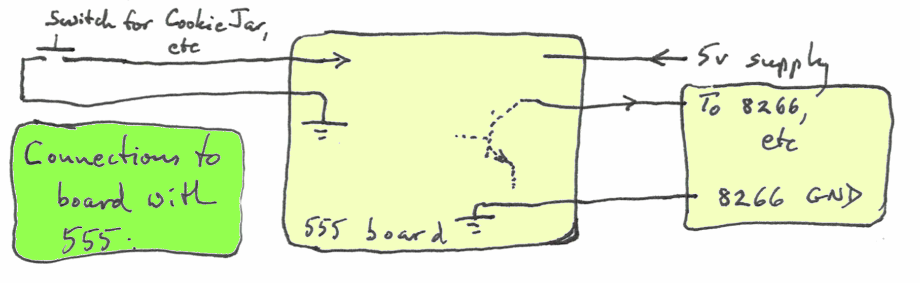
A messy bit... sorry. No time! I spent the time because I thought it would be useful to you. If you can't be bothered, I'll refund what you've paid me for these ideas.
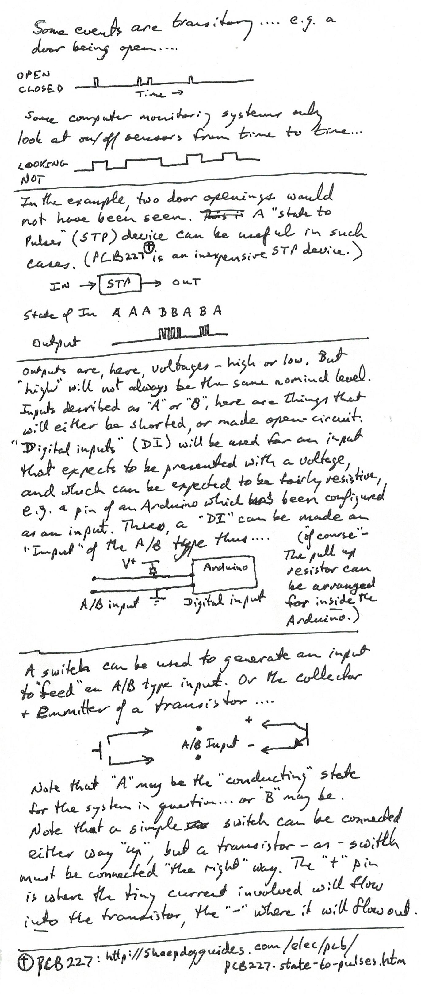
In the following image of some handwritten notes, there are some links. They appear again in "clickable" form after the image...
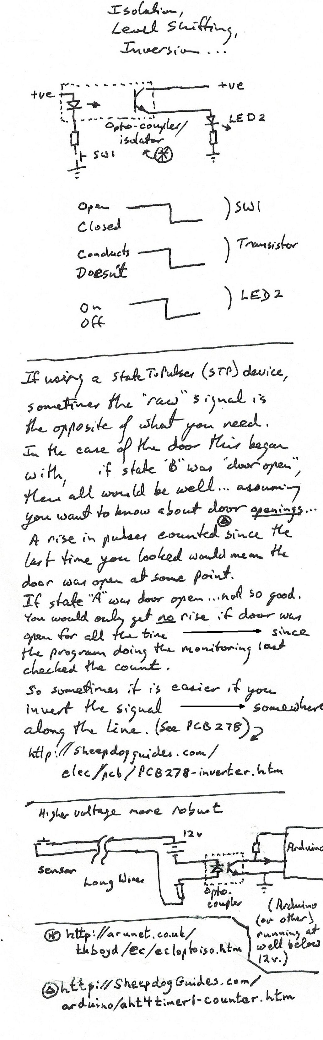
Here are some of the links in the image above...
http://sheepdogguides.com/elec/pcb/PCB227-state-to-pulses.htmIf it was useful, please link to it, please mention at forums? Link to this page?
If you spot a flaw, or there are related matters I should talk about here, emails with feedback are always welcome. Details below.
This page is meant for hobbyists. A lot of pleasure (or inspiration to improve your design!) can be had from comparing the results your electronic rainfall monitors record with the results of a simple traditional rain gauge.
You may want to check other pages of this site for things which might have appeared on this page, but were either mis-sited or had a more general relevance.
The search engine merely looks for the words you type, so....
* Spell them properly.
* Don't bother with "How do I get rich?" That will merely return pages with "how", "do", "I"....
Please also note that I have two other sites, and that this search will not include them. They have their own search buttons.
My site at Arunet.
My Sheepdog Guides
site.
This is just one of the guides I have published on the net. Please visit any of the following that relate to interests you have....
Help with the excellent free database included as part of the free, multi platform Libre Office/ Open Office.
Lazarus Tutorials. (Similar to Delphi)
Electronics for hobbyists and schools
Main Home Page
Here is how you can contact this page's author, Tom Boyd. Please cite "SheSof/SC2sPulseTrain.htm"
![]() Page has been tested for compliance with INDUSTRY (not MS-only) standards, using the free, publicly accessible validator at validator.w3.org. Mostly passes.
Page has been tested for compliance with INDUSTRY (not MS-only) standards, using the free, publicly accessible validator at validator.w3.org. Mostly passes.
AND passes...

-- Page ends --