HOME > >
SENSING AND CONTROL MAIN PAGE > >
WIRING > >
1-WIRE
Sensing and Control for hobbyists and schools: Connecting using 1-Wire (aka MicroLan): Signal location conventions
Page URL: SC3wms.htm
(Farther down this page, you will also find some comments on ethernet cabling, in particular on how a LAN cable can also carry 1-Wire signals.)
Which wires....?
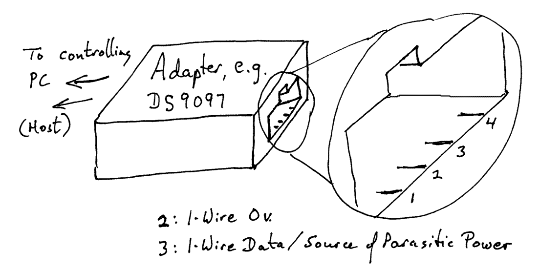
YOU are responsible for what YOU do. Don't complain to me (INFORM me, but don't complain) if you have problems when you use anything in my sites. I won't even refund the zero dollars you've paid! But! Having said that, the following diagram shows you which pins from a 1-Wire adapter carry which signals....

N.B.: Even if I've numbered the pins correctly, you may come across diagrams where they are numbered in the other order. Often, I have an adapter to be connected to a 1-Wire module via screw terminals. I plug in the adapter, then plug in a cable (not attached to the module), being careful not to short the ends which will soon be attached to the module. I then put a voltmeter on the ends of the cable. The +5v end goes to the 1-Wire Data/Power connection on the module.
So what are pins 1 and 4 used for?
Beware! Different people use them for different things!! Sometimes they are connected to nothing, other times they carry a regulated 5v (not always the same way 'round), or an unregulated higher voltage. Sometimes, e.g. the AAG wind speed/ direction sensor, shorting pins 1 and 4 on the 1-Wire module effects an option choice, and feeding a voltage in either can be harmful.
Forgive me covering something for really new beginners? Many "1-Wire" chips can be connected to their controller with just two wires. One is the "ground" or "zero volts" wire. The other is the 1-Wire "Data" wire... but it is also the source of the voltage which makes the 1-Wire chip work. If you measure the voltage between the two wires, most of the time it will be 5 volts. Many 1-Wire chips are able to operate simply by using that voltage. Inside the chip is a small capacitor which acts like a tiny "rechargeable battery" to tide the chip over the brief moments when the voltage between the two wires is not 5 volts. This is referred to in Dallas documentation as parasitic powering.

March 2021: STOP PRESS!
How strange! After 16 years, in 3/21, I took myself to this, my own page, because i was wiring up a cable for 1-Wire. And suddenly had a crisis of confidence! THIS MAY NOT BE RIGHT.
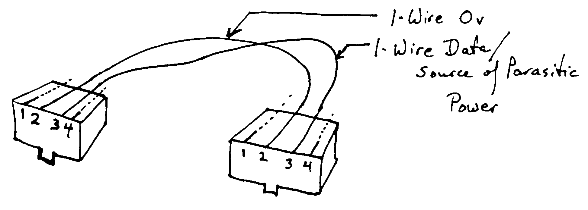
Just BE CAREFUL... The things you are inter-connecting TYPICALLY have their GND and "1-Wire data/parasitic" power on the center two pins, if using RJ-11 connectors.
Me? I would design boards to be daisy-chained so that both sockets had the same signal on the same pin. I THINK that's what most 1-Wire designers do.
I THINK the interconnect cable for such systems would be a "straight through". BUT THE CABLE ABOVE... is?... CROSSING THE SIGNAL OVER?? AND NO ONE HAS COMPLAINED!!! I hope that means no one has wasted their time on bad information... if that's what this is.
The more I think about this, the worse my headache gets.
So, I'm going to leave you with: "BE CAREFUL".
I AM at least still confident that you WILL find cables meant for plugging phones in (in the USA) in both varieties... "straight-through" and "crossover".
(Before the 3/21 crisis of confidence discussed above....) I believe(d) that what you see above is the "standard" use of the conductors in a RJ-11 plug, when used for 1-Wire systems is as follows. I KNOW that an "ordinary" telephone plug-to-plug lead is NOT ALWAYS done this way... if you're thinking of using one of them, CHECK! In any case, all of this is one of those things that (for me at least) are easy to get back to front. In fact I've really written it up here for my own reference from time to time.
An RJ-11 plug is the roughly 1cm x 1cm plug / socket system used for US telephones. They are also found at the computer end of many modem cables. RJ-45: Similar plugs, but with 8 contact points. Used with Ethernet. On an RJ-45, the Dallas "0 volt" and "Data" lines are still the central two contacts. If you are making up your own cable, be sure to serve those two contacts with the two members of a single twisted pair. If you want to use the cable to also be useable as an Ethernet patch cord, be sure to assign the members of the pairs correctly.)
If you wire up your RJ-11 (or RJ-45) patch cables as above, they can be used between normal 1-Wire modules, or between the adapter to the host PC and the first module in the MicroLan. (Remember what I said above about the various uses people make of the conductors other than the middle pair.) It won't matter which way "around" you plug in the cable. Isn't that tidy! If you have a sensor module with two RJ-11 sockets on it, IF it is intended to be used in a chain, (i.e. you are supposed to be able run a patch cord from your DS9097 into one of them and a second patch cord from that module to one of the RJ-11 sockets on then next sensor board, etc,) then it doesn't matter which socket you use on any of the modules. There is no "in" or "out" socket.
BUT!! BE CAREFUL!! It does depend on what the designer has put that RJ-11 on the board for, though he/ she would be foolish to use an RJ-11 around 1-Wire devices if it wasn't meant for connecting them via the 1-Wire protocol.
Going back to the topic of parasitic power: Some people suggest that it only works reliably in limited circumstances. It is not unusual for designers of 1-Wire based systems to use one or both of the outside contacts on the RJ-11 to supply power. BEWARE: Some devices you can buy for 1-Wire work HAVE MADE CONNECTIONS between those outer contacts and the 1-Wire signals. I think Simon's hubs do, for example. Take care!)
Because I have and like the Dallas / AAG wind device, I'm going to put my power line on the outside conductor on the "Data" side of the cable in my 1-Wire LANs. This will avoid a hassle with the fact that the wind device ties the other outside conductor to the 1-Wire Zero volts/Ground line.

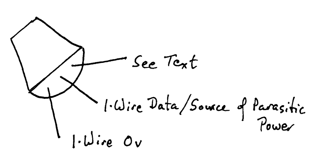
The diagram above shows you which signals are on which pins of the DS1820 and of the DS2405. In the case of the former, the "See Text" pin can be tied to the Dallas 0 volt line if you want to power the chip parasitically, or it can be fed 5v to make the MicroLan more reliable. If the chip is a DS2405, the "See Text" pin is for the one bit of input or output that the chip provides.
Ethernet and 1-Wire.. shared cables....
Admission: This information is NOT tested, is here primarily for "peer review". If anyone sees problems with the following ideas, please let me know! Note the comments elsewhere about the use by some 1-Wire hardware makers of pins other than the "basic" middle two for 1-Wire purposes. (I have thought quite carefully about the following, researched it somewhat... is just is not as definitive as most of the things I put up on the web!)
I ran some Cat 5 cable from my office to my front door in order to hook up a IP Cam. (IP Cam: Like a webcam, but it connects to PC across an Ethernet LAN.) I thought it would be nice to use a pair of wires in the same Cat 5 cable to extend my 1-Wire network to the front door. It struck me as possible that Ethernet wasn't using all 8 wires. Especially as I am not making use of Power-Over-Ethernet.
My researches turned up a couple of things.
a) My numbering scheme for the RJ-11 (diagram above) may be wrong. It may (well) be that the numbers are reversed i.e., the left hand connector, when the plug is viewed as above, would (perhaps) normally be called "4".
Using the numbering it seems I SHOULD have used, and starting with the outside pin as "1" and going across the RJ-45 2,3,4,...8, I've found websites which say....
For a normal (i.e. NOT crossover) ethernet patch cable (i.e. from LAN hub to PC), you wire pin 1 of the RJ-45 on one end of the cable to pin 1 on the other end of the cable. Likewise, you wire 2 to 2, 3 to 3 and 6 to 6. You (I think!) don't need pins 4 and 5 (the middle two connectors), so those wires can be used for 1-Wire.... which, happily, presumably NOT by coincidence, are the two pins we normally use for 1-Wire... the middle two, be it the 4 way RJ-11 or the 8 way RJ-45... I just haven't (previously) tried to use one piece of Cat 5 to carry both 1-Wire and Ethernet!!
Something else you should know: Within a Cat 5 cable, the wires are not all "the same". They are in twisted pairs. The blue colored wire and the white-with-blue-stripe colored wire, for instance, are twisted around each other. Etc. So within the Cat 5 cable, you have 4 pairs of wires. To get good results from 1-Wire or Ethernet, you should connect the right wire to the right pin, so that certain things go down a single twisted pair. I believe the "standard" use of the pins is as follows:
(Remember: In the following, unlike the diagrams above, if you are looking at the plug "end on" (cable trailing away from you), with the connectors on the top side, the RIGHT hand pin is "pin 1".)
1: White with Orange stripe
2: Orange
3: White with Green stripe
4: Blue
5: White with Blue stripe
6: Green
7: White with Brown stripe
8: Brown
One last little bit of info, in case the reference to "crossover cable" (above) brought you here from Google or other:
A crossover cable allows you to connect two Ethernet-capable devices to one another for the world's smallest "LAN". You can dispense with the normal hub, if you use the crossover cable. (And the other side of that coin is: Don't use a crossover cable to connect anything to a hub!)
Again: I'm assuming you don't need Power-Over-Ethernet. The minimum necessary connections in a crossover cable are, I believe, as follows:
1-3
3-1
2-6
6-2
(You read the first line as follows: "Connect pin 1 of the plug at one end of the cable to pin 3 on the plug at the other end of the cable.)
I'm still numbering the pins NOT as in the diagrams farther up the page.
A final observation regarding crossover cables: If you had a normal "patch" cable, i.e. a cable to go from, say, a router to a PC, and you had a small adapter, consisting of an RJ-45 socket on one side plus an RJ-plug on the other, to plug onto the end of the cable, then the cable + plug would "be" a "crossover cable"... but when a day came that you didn't need the crossover cable, you could just unplug the adapter from the end, and, hey presto!, you have a normal LAN cable to use until the next time you need a crossover "cable". (I don't know where you buy such an adapter. One would be easy enough to make up. Please let me know if you discover a commercial source?)
Click this to search this site without using forms, or just use......
The search engine merely looks for the words you type, so....
* Spell them properly.
* Don't bother with "How do I get rich?" That will merely return pages with "how", "do", "I"....
Please also note that I have three other sites, and that this search will not include them. They have their own search buttons.
My site at Arunet.
Please also note that I have two other sites, and that this search will not include them. They have their own search buttons.
My SheepdogSoftware site, http://SheepdogSoftware.co.uk.
My SheepdogGuides site, http://SheepdogGuides.com.
Ad from page's editor: Yes.. I do enjoy compiling these things for you...
hope they are helpful. However.. this doesn't pay my bills!!! If you find
this stuff useful, (and you run an MS-DOS or Windows PC) please visit my
freeware and shareware page, download something, and circulate it for me?
At least (please) send an 'I liked the parallel port use page, and I'm
from (country/ state)' email? (No... I don't do spam)
Links on your page to this page would also be appreciated!
Click here to visit editor's freeware, shareware page.
Other projects
This is just one of the guides I have published on the net. Please visit any of the following that relate to interests you have....
Delphi Tutorials
Pascal programming tutorials
Electronics for hobbyists and schools
Main Home Page
To email this page's editor, Tom Boyd....
Editor's email address. Suggestions welcomed! Please cite the page's URL, "sc3wms.htm".
 Page has been tested for compliance with INDUSTRY (not MS-only) standards, using the free, publicly accessible validator at validator.w3.org. Mostly passes.
AND passes...

One last bit of advice: Be sure you know all you need to about spyware.
. . . . . P a g e . . . E n d s . . . . .


![]() Page has been tested for compliance with INDUSTRY (not MS-only) standards, using the free, publicly accessible validator at validator.w3.org. Mostly passes.
Page has been tested for compliance with INDUSTRY (not MS-only) standards, using the free, publicly accessible validator at validator.w3.org. Mostly passes.